
Biomechanics of Cancellous Screw
Vol 2 | Issue 2 | May – Aug 2016 | page:56-62 | Anand J Thakur
Author: Anand J Thakur [1]
[1] Irla Nursing Home & Polyclinic, 189, Swami Vivekanand Road, Irla,Vileparle, west, Mumbai -400 056, Mumbai
Address of Correspondence
Dr. Anand Thakur
Irla Nursing Home & Polyclinic, 189, Swami Vivekanand Road, Irla,Vileparle, west, Mumbai -400 056, Mumbai
Email: thakurajt@gmail.com
Abstract
Understanding the basics of implant biomechanics is the foundation of orthopaedic surgery and practice. Bone screws are the most commonly used implant in orthopaedic trauma surgery. This article aims to review the biomechanics and the engineering principles of a bone screw and also discuss the various avatars of a bone screw with main focus on the cancellous screws.
Keywords: Cancellous screws, biomechanics, orthopaedic trauma.
Introduction
A bone screw is used for internal fixation more often than any other implant; it serves to hold together two or more objects and to lag i.e. compress two objects together. Though it appears a simple device, a great deal of complex engineering technology has contributed to its current design. There are two major types of screw: the wood screw and the machine screw. To understand the difference between the types, one should recapitulate Newton’s Third Law of motion: ‘every force has an equal (in magnitude) and opposite (in direction) reaction force’. Once the screw is set, the force pulling the two components together must be generated by an elastic reaction somewhere within the screw or in the material into which it is inserted. A wood screw has relatively large threads and is usually tapered; it is put into a material with a small pilot hole. The threads of the screw form their own mating threads by compressing the material. The screw is much stiffer than the wood into which it is inserted; the spring or elastic force therefore arises from the deformation of the surrounding material, not the screw. It is this force that draws together the two wooden surfaces held by the screw (Fig.1 A).
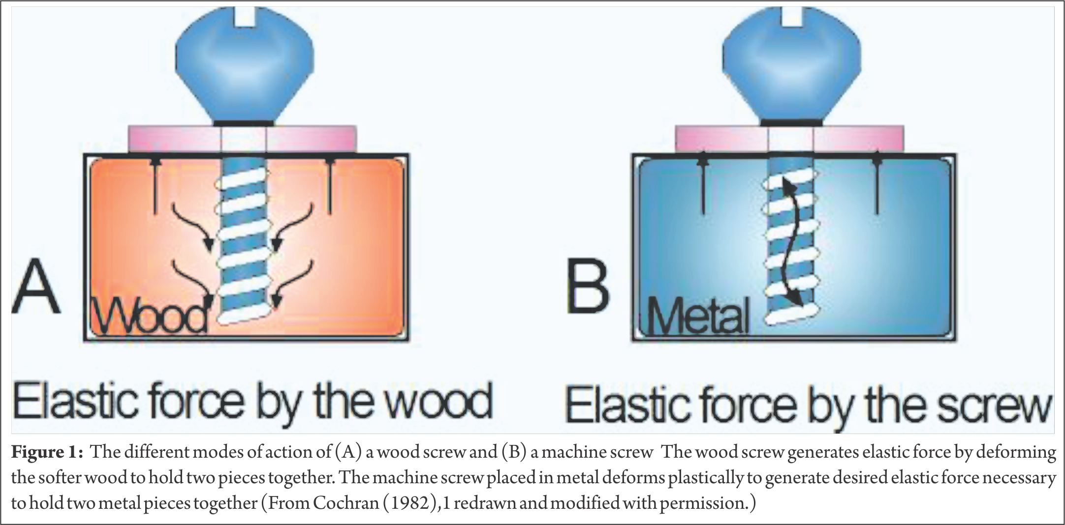
A machine screw differs from a wood screw in that it is intended to be placed into a hole in which threads have already been cut by a tool known as a tap. A pilot hole matching the size of the screw core is first drilled and then tapped by a tool that is twisted into the hole, cutting the threads with a sharp edge. In the case of a machine screw placed in metal, the elastic reaction which lends the screw its compressive force comes primarily from the shank of the screw itself. The machine screw, rather than the much larger cross-section of the surrounding metal, deforms plastically (Fig.1-B). A cancellous bone screw is a modified wood-type screw. It is inserted into an untapped pilot hole; the spring reaction comes from the cancellous bone as it is deformed during the thread forming process. A cancellous screw has four functional parts: head, shaft, thread, and tip (Fig.2).

1. The screw head serves as an attachment for the screwdriver. It has a recessed hexagonal socket (Hex head). A hexagonal head driver makes a strong and alignment-sensitive connection with the screw and offers a good lateral guidance that allows ‘blind’ insertion and removal. The driver tip snugly fits in the screw head and is unlikely to slip out or distort the head. Thus the operator knows the inclination of hex screw of which only the head protrudes from the bone because the screwdriver by necessity aligns with screw axis. The torque transmission is independent of axial thrust and thus does not compromise initially unstable reduction of the fracture fragments. The countersink, or the under-surface of the head, is hemispherical which allows the screw to be angulated in all directions within a washer or the screw hole of a plate while maintaining concentric contact between the screw and the side of the plate. Its disadvantage is its prominence when used without a plate. The screw head serves two functions. Firstly and obviously, it provides the means of applying torque (twisting force) to the screw. Secondly, it acts as a stop. As the head comes in contact with the bone surface, the translational motion of the screw stops and the torque transforms to tension in the screw, which in turn induces compression between the two surfaces. Compression develops only after the translational motion of the screw stops.
2. The shaft or shank is the smooth link between the head and the thread. The shaft length is variable and in a cancellous screw it is significant. Screws with long shafts are used as lag screws. The smooth shaft has no purchase in the proximal segment of the pilot hole and ensures compression by lagging. A significant length of the shaft has threads; a screw thread can be visualized as a long inclined plane or a wedge encircling core (root). The core diameter or root diameter represents the narrowest diameter of the screw across the base of the threads. The torsional strength of a screw varies with the cube of its root diameter. Doubling the root diameter of a screw increases the extent of torque that it can withstand by a factor of 8.
3. The standard cancellous screw has a single thread. The pitch is the distance between the adjacent threads (see Fig.2 B). A cortical screw with a fine thread has a small pitch whereas a cancellous screw with a coarse thread has a large pitch. The stronger the bone (cortex), the smaller the pitch; the weaker the bone (cancellous), the larger the pitch. In an AO large fragment cancellous bone screw the pitch typically measures 2.75 mm; this is also expressed as the number of threads per inch (tpi): 9.2 tpi. Outside diameter of a cancellous screw refers to the diameter across the maximum thread width and affects its the pull-out strength. The larger the outside diameter, the greater the resistance to pull-out. Up to a reasonable limit, the larger the size and surface area of the threads that are engaged, the greater the holding power. This explains why most ‘cancellous’ screws have a wide diameter thread.
4. A corkscrew tip is used in cancellous screws where the tip clears pre-drilled hole. The cancellous screw forms its own threads by compressing the thin walled trabecular bone. Thread-forming tip is suitable only for use in a cancellous bone,
The cancellous bone screw is a thread-forming, self-tapping screw. The term ‘self-tapping screw’ refers to a screw which is inserted directly into a pre-drilled hole without first tapping a thread. Self-tapping screw may further be subdivided into thread-forming and thread-cutting screws. The screw thread forms its own mating bone thread by compressing the soft cancellous bone. A tap should not be used to insert a cancellous screw – a cancellous screw inserted in a tapped hole has lower pull-out strength than one inserted in an untapped hole because tapping removes cancellous bone from the hole, and effectively enlarges it (Fig.3).
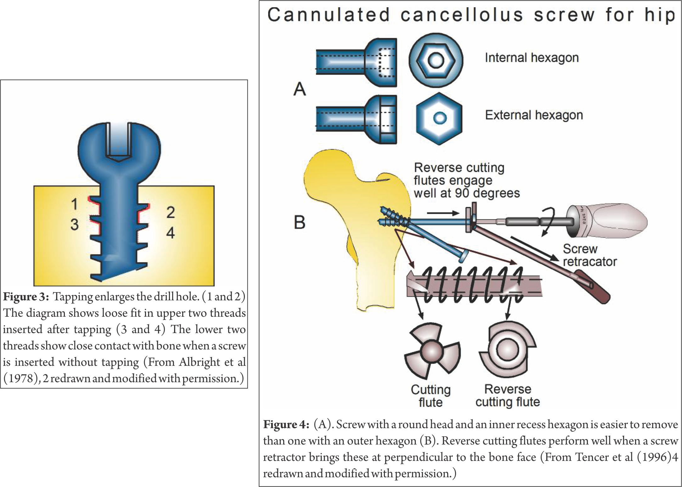
The amount of bone removed by tapping increases as the density of bone decreases; the mean volume increase is about 25%. When a cancellous screw is to be inserted first through hard cortical it is necessary to tap the cortical bone. Cancellous taps are provided for this reason alone. The smooth shaft of the cancellous bone screw provides the lag effect without the need for over-drilling. This becomes significant in the larger 6.5 mm screws, where a very large hole would need to be drilled in the near cortex to produce a lag effect. Cancellous screws are available as fully and partially threaded screws. A fully threaded cancellous screw is used as a placement screw to fix a bone plate in metaphyseal and epiphyseal regions. A partially threaded cancellous screw is used as a lag screw. Cannulated cancellous screws are useful for exact placement. A cannulated screw is used over a guide wire for precise insertion in metaphyseal or epiphyseal site to eliminate the problem of having to remove and reposition an incorrectly placed screw. A guide wire accurately visualizes the path of the screw. In addition, the guide wire maintains the reduction and controls the fracture fragments. If guide wire position must be changed, it can be done without enlarging the hole and sacrificing holding strength of the bone. Final placement of the screw requires use of cannulated drill, a cannulated tap, and a cannulated screwdriver. Cancellous cannulated screws come in large and small sizes. Large cancellous cannulated screws are used to fix fractures of the femoral neck, femoral condyle and tibial plateau. Small cannulated cancellous screws are employed for fixation of the distal radius, distal humerus, distal and proximal tibia and carpal scaphoid. A larger root diameter as compared to an equivalent non-cannulated screw is needed to accommodate the central bore of a cannulated screw. This effectively decreases the volume of bone between the screw threads and to some extent curtail its holding power. The cannulated screw head has either an internal hexagonal recess to work with a cannulated screwdriver, or an external hexagonal or square head and a cannulated wrench (Fig. 4).
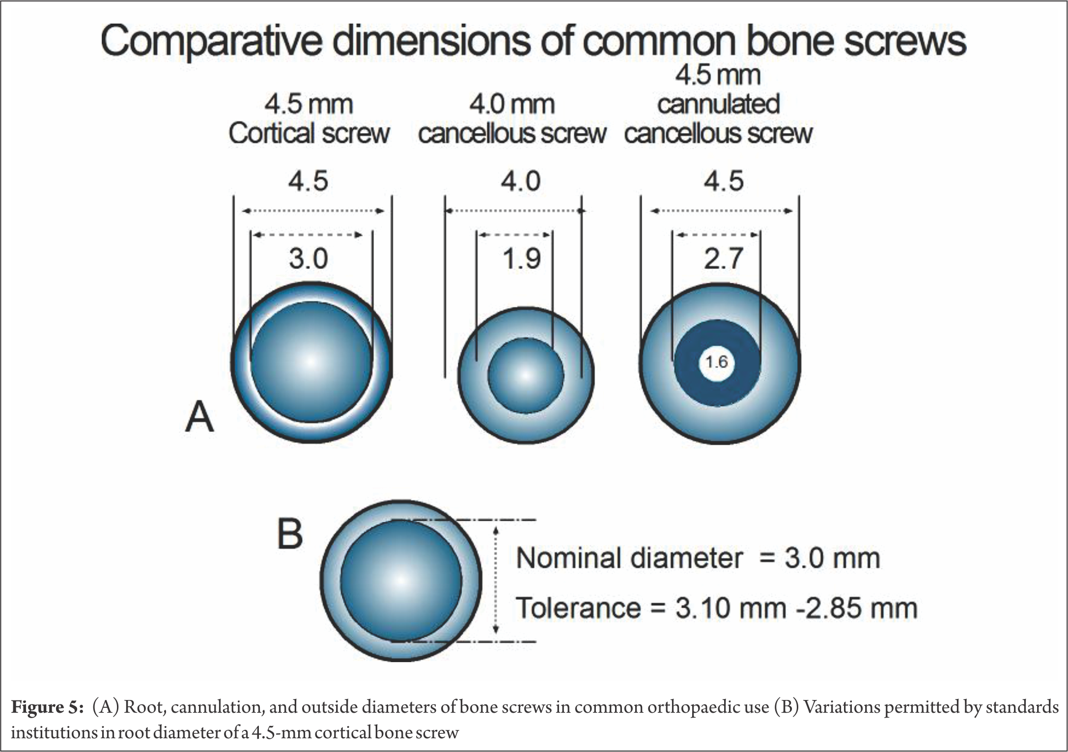
The internal recess design allows use of a slim screwdriver, and permits a spherical outer shape to the screw head. This can be important in screw removal. Bone growing around a screw head with an external hexagonal head makes removal difficult, since bone must be removed to allow engagement of a wrench. If two external hexagonal screw heads touch, they may lock. The advantage of using the external hexagonal head is the strength provided to the coupling with the driving wrench. The round head with an internal recess puts more demand on the screwdriver’s tip. The screwdriver hexagonal tip must be small enough to fit within the recess in the screw head, yet itself must be cannulated, leaving little material in it. In addition, strength of the screw head-shaft junction is important. The internal hexagonal recess removes material from the head. If this recess is too deep, strength may be lost at the head-shaft junction. To maintain the strength, the diameter of the shaft of a cannulated screw is often designed slightly larger than that of a solid screw of comparable size. Since the stiffness of a cylinder in bending is a function of the third power of its radius, a small increase in the outer radius of the shaft will compensate for the cannula. An example of medium-sized screw of comparable dimensions is shown in Fig 5. Cannulation does not appear to be a problem in the larger screws, but in a smaller screw leaving a cannulation large enough for stiff guide wire, may require the shaft diameter to be significantly increased or the screw will be considerably weaker. There is a misconception that a solid screw is stronger than a cannulated screw of equivalent outer thread diameter. The 6.5-mm cannulated screw usually has a slightly larger shaft (root) diameter than its solid 6.5-mm counterpart. A solid 6.5-mm may have a 3.0-mm thread root diameter, while the 6.5-mm counterpart has a root diameter of 4.8-mm. If the cannula is 2 mm in diameter, the area and polar moments of inertia of the cannulated screw would be 102.6 mm and 514.8 mm compared with 27 mm and 81 mm: i.e. 3.8 and 6.4 times greater respectively than those of the solid screw. A cannulated screw must have a larger root diameter than the solid screw to allow room for the cannula. However, this does decrease its holding power, because of smaller thread depth. Clinically cannulated screws appear to function well and have more than adequate holding power. A cannulated screw for cancellous bone should be self-cutting and self–tapping. The screw tip cuts only when rotated clockwise and is blunt when turned counter-clockwise (removal direction). Such a tip is advantageous in percutaneous procedures. After the guide pin is place, the screw is advanced through the soft tissue while turning it in a counter-clockwise direction. The tip doesn’t cut or wind the soft tissues. When cortex is reached, the rotation is reversed to clockwise, allowing it to cut into the bone. Successful insertion of a cancellous screw starts with the drilling of a pilot hole and ends with the screw achieving a firm purchase in the bone. A pilot hole can be drilled with a Kirschner wire, bur or drill bit. A drill bit (twist drill) is normally used. During drilling a small amount of bone is lodged in the drill’s flutes and is removed; in porotic bone such a loss is detrimental. If a K-wire is used in porotic bone to drill a hole, it preserves the precious bone which is not dislodged but compacted around the pilot hole. Heat is generated while drilling. The energy used to drive the drill bit is converted to heat and may cause thermal damage the bone. Kirchner wires produce more heat than a drill bit. As the pin shaft is smooth, there is no way of eliminating the debris which is inevitably compressed against the wall of the hole leading to an increase in friction and higher temperatures. Heat production is directly related to speed and increases markedly above 500 rpm, which is the optimum recommended speed for a pin. Necrosis of osteocytes can be produced in the long bones of rabbits by exposure to 47°C for one minute. While making a pilot hole, it is essential to use saline as a coolant to keep the bone viable. Irrigation with normal saline solution (‘saline’) is effective and should commence simultaneously with drilling as the temperature increases almost instantaneously at the start of the act and much more slowly thereafter. A washer is often used with a cancellous screw to prevent the screw head from burying into the thin cortex overlying the cancellous bone (Fig. 6). The flat side of the washer rests on bone while its countersunk side matches the underside of the screw head.

In the initial phase of insertion the bone threads in the near cortex may easily get distorted as the moment arm of the torque is large and the screw is largely unsupported. Likewise in osteoporotic bone a substantial torque produced by a large screwdriver handle also can easily destroy the bone threads produced by a self-tapping or cancellous screw. If excessive torque is required to insert a self-tapping screw, it should be removed and its flutes be cleaned before reinsertion. A self-tapping screw may be inserted with a powered or hand operated drill machine.
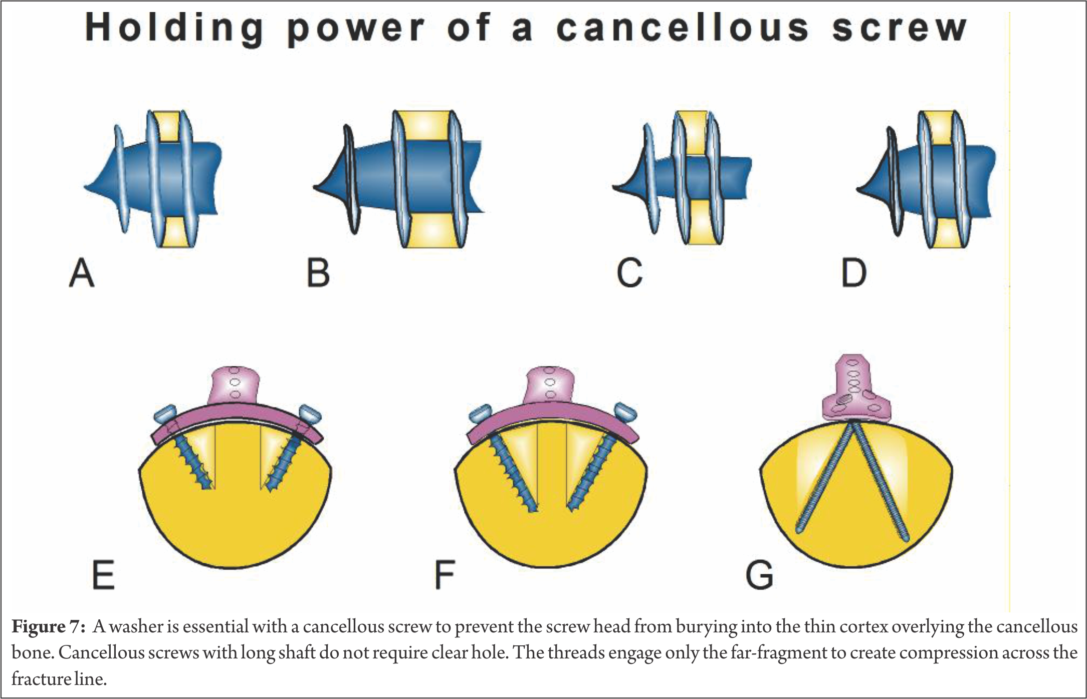
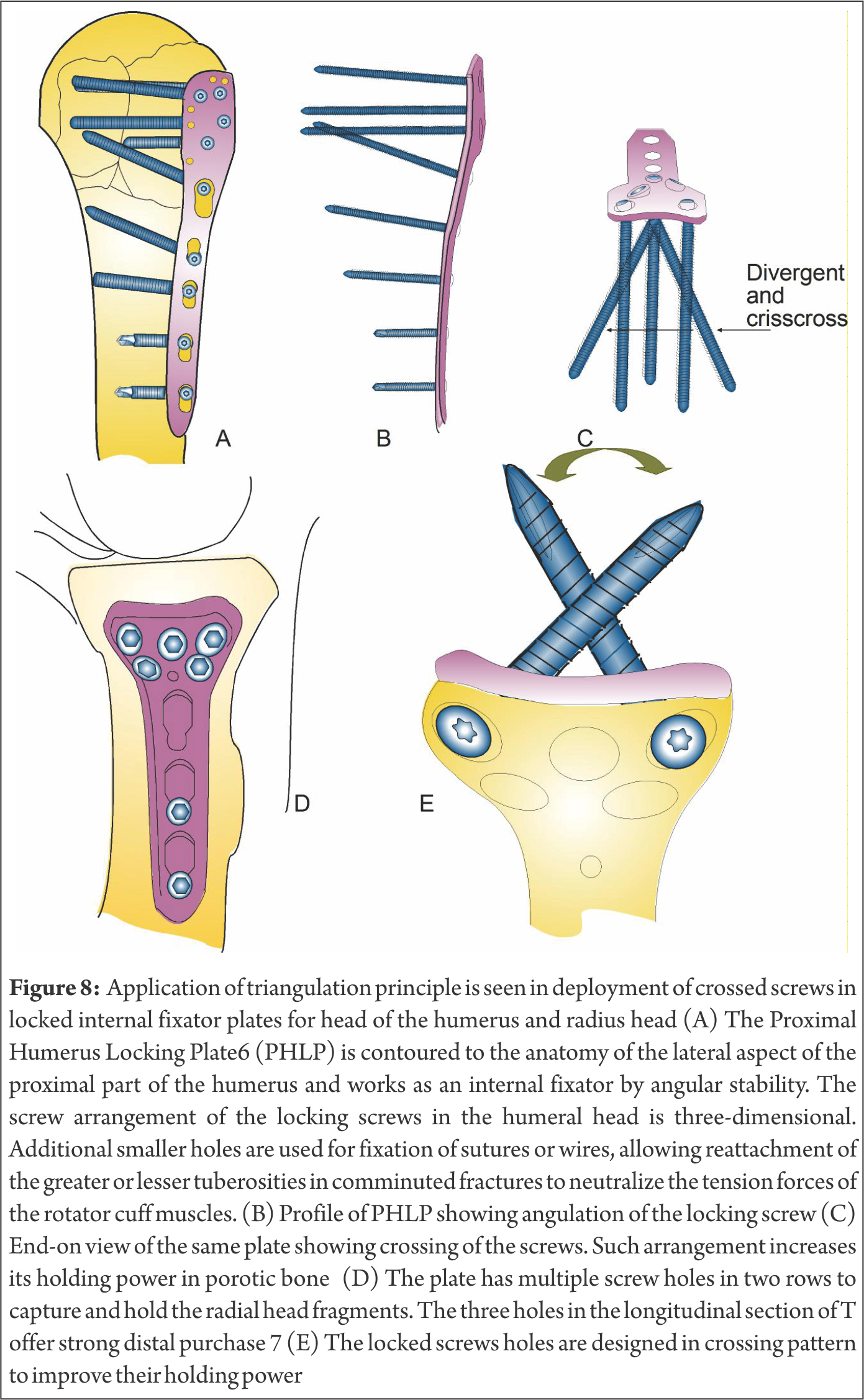
The accuracy of power insertion is better than that of manual insertion. In very hard bone, a STS may be handled similar to a tap during insertion. The heat generated during insertion is independent of the machine speed. The screw is centred and inserted perpendicular to the hole in a plate. When a screw is driven-in off-centre it may jam or bone threads may get damaged. Besides, bending moments may be created which may damage the bone threads and perhaps weaken the screw. The so-called holding power of the screw depends on several factors like, thread shape, its depth, its angle factor, the number of threads engaged (bone thickness), the size of the hole and the shear strength of bone. In addition, when the screw is implanted in the bone, the tissue reactions and the bone growth also affect the holding strength; in general, the holding power of the screw is proportional to the bone volume between threads, the length of the screw and its triangulation with the plate (Fig. 7). The triangulation principle is used in locked internal fixator plates for head of the humerus and radius head (Fig. 8)
Screw vs Bolt
A screw is an externally threaded headed fastener which is tightened by applying torque to the head, causing it to be threaded into the material it will hold. A bolt is also an externally threaded headed fastener, which is used in conjunction with a nut and is tightened or released only by twisting a nut (Fig. 9). To obtain reliable and repeatable fastener torque the bolt / nut combination should always be tightened by holding the bolt head stationary and turning the nut 8. A further clarification aimed at disambiguation is available 9. Bolts are headed fasteners having external threads that meet an exacting, uniform bolt thread specification such that they can accept a non-tapered nut. Screws are headed, externally threaded fasteners that do not meet the above definition of bolts.

A screw is designed to cut its own thread; it has no need for access from or exposure to the opposite side of the component being fastened to. A bolt is the male part of fastener system designed to be accepted by a pre-equipped nut of exactly the same thread design; it needs access from or exposure to the far side of bone being fixed. Cancellous and cortical screws are unsuitable to be used as bolts; a specific implant is mandatory.
References
1. Cochran G V B 1982 A primer of orthopaedic biomechanics. Churchill Livingstone, New York.
2. Gozna E R, Harrington I J, Evans D C 1982 Biomechanics of musculoskeletal injury. Williams & Wilkins, Baltimore
3. Albright J A, Johnson T R, Saha S 1978 Principles of internal fixation.
4. Tencer AF, Asnis SE, Harrington RM, Chapman JR 1996 Biomechanics of cannulated and noncannulated screws. In Asnis SE., Kyle RF. Eds. Cannulated screw fixation New York Springer-Verlag pp15-40
5. Lastra J J, Benzel E C 2003 Biomechanics of internal fixation In: Vaccaro AR et al Eds. Principles and practice of spine surgery. Mosby, St. Louis pp 43-65
6. Synthes, Switzerland
7. Burkhart KJ, MD, Muelle LP , , Krezdorn D, Appelmann P,. Prommersberger KJ, Sternstein W, Rommens PM, 2007 Stability of Radial Head and Neck Fractures: A Biomechanical Study of Six Fixation Constructs With Consideration of Three Locking Plates J Hand Surg;32A:1569–1575.
8. R. Paul Haight 2012 http://engineerexplains.com Accessed 8 October 2014
9. http://en.wikipedia.org/wiki/Bolt _(fastener)#Bolts_vs._sc.
| How to Cite this article: Thakur AJ. Biomechanics of Cancellous Screw. Trauma International May – Aug 2016;2(2):56-62 |
